11.3 Characterization of Fractured Bedrock, United Kingdom
Contacts
HRSC Targets Impacts
High resolution site characterization (HRSC) enabled a targeted site investigation that delineated the depths of TCE impacts in near real time (optimizing drilling meterage) and demonstrated the presence of this solvent both within the fractures and diffused into the rock matrix. This information is critical to fully understand the CSM, improve remediation performance, and gain agreement of endpoints with the regulatory authorities in line with the client’s objectives.
Kathryn Johnson
Senior Consultant, ERM
+44131 2216783
[email protected]
Kevin Leahy
Technical Director, ERM
+441865 384855
[email protected]
James Baldock
Technical Director, ERM
+441865 384907
[email protected]
Site Description
The study site is an operational manufacturing facility, located in the United Kingdom (UK). A preliminary site investigation undertaken in April 2015 as part of a pending transaction identified impacts to groundwater from TCE, with concentrations detected at around 30% of the maximum solubility for TCE, suggesting the likely presence of DNAPL. In addition, TCE had been detected at downgradient third-party receptors. The study site had a long history of TCE use and several potential source locations were identified, including external bulk storage tanks, solvent transfer pipes and internal degreaser locations. Due to the high concentrations of TCE detected and the impacts upon third-party receptors, remediation was considered likely to be required.
Lithology/Bedrock Description
The study site is located on a hilltop, with thin soils over unweathered, fractured Upper Devonian shales/slates. These were folded and thrusted in the Carboniferous Variscan Orogeny, and a thrust plane was intersected at 58 m below ground level in the deepest monitoring well. Folds and thrusts verge to the north, whilst the main set of slatey cleavage strikes east, dipping at 60° S. Quartz-chlorite-calcite veins are present in tight, high angle sets, and in more massive, vuggy veins subparallel to the thrust and within fold cores.
Hydrogeology
Groundwater monitoring carried out between April 2015 and August 2015 indicated groundwater was present at between 12.2 and 15.6 m below ground level (m bgl). Groundwater levels showed high variability, with differences of up to 2.9 m in water level seen between monitoring rounds. Groundwater flow is complex within the fractured bedrock, but the overall bulk flow direction is to the east towards off-site receptors.
Contaminant Nature and Extent
The primary contaminant at the study site was TCE, with maximum concentrations in groundwater of 328 mg/l. TCE breakdown products, cis-1,2-dichlorethene and vinyl chloride were also detected at maximum concentrations of 3.7 mg/l and 0.07 mg/l, respectively. Traditional site investigation work in April 2015 identified impacts adjacent to the eastern boundary of the site based on a limited number of widely spaced boreholes; the nature of the bedrock had also not been fully assessed at this stage.
The study site had a long history of TCE use (45 years), however the potential date of any TCE release was not known.
Site Characterization
Site investigation activities in April 2015 had identified impacts to groundwater from TCE, which were likely to need future remediation. When designing the next phase of investigation there was no potential to investigate likely source areas inside the operational facility. The objective of the investigation was therefore to investigate accessible external locations to vertically and laterally delineate the contaminant plume and investigate pollutant linkages between the site and third-party receptors. The work was also to be completed within a short timeframe. Complex geological and hydrogeological conditions were anticipated due to the presence of fractured bedrock and the maximum depth of contaminant impacts was unknown. Based upon regional geological information impacts had the potential to extend to depths of over 100m bgl.
Site Characterization Approach/Tools
Traditional site investigation techniques were largely unsuitable for detailed site characterization, due to the fractured bedrock geology and likely complex contaminant distribution. With traditional techniques, rock samples would need to be sent to an off-site laboratory, with sample transport and laboratory turnaround times meaning results would not be available to inform the drilling depth and well installation for several days afterwards.
Therefore, to be able to rapidly collect data and install targeted groundwater monitoring wells a complimentary suite of high resolution site characterization (HRSC) techniques were chosen:
- CORE Discrete Fracture Network Approach (Core DFN), as developed by Beth Parker (2007) and provided by Cascade Technical Services, coupled with an on-site laboratory for VOC analysis of rock samples
- detailed structural and geological logging of cores (structural frequency analysis)
- down-hole geophysics (acoustic televiewer with automated structure identification and orientation)
- background fluorescence analysis (BFA)
These techniques were supplemented by traditional groundwater monitoring and then synthesized to develop a conceptual site model for the fractured bedrock. The drilling and on-site laboratory work were completed in two weeks and followed by traditional groundwater monitoring.
Results–Geology
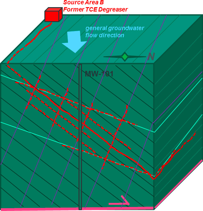
The results of the acoustic televiewer, structural logging and frequency analysis and the Core DFN data allowed orientated structural features, such as fractures and bedding planes to be compared with TCE distribution to develop a fractured bedrock CSM. The fractured bedrock structural features are shown in Figure 11-13.

Figure 11-13. Fractured bedrock structural features for study site.
Note that the green parallel lines are bedding and bed parallel fractures (dipping 45°N), purple are slatey cleavage (dipping 60°S) and pale blue are a low angle open fracture set (dipping 30°N). The thrust is schematically illustrated as the pink line. TCE impacts in fractures are schematically indicated in red lines, solid to indicate >10% solubility, dashed to indicate lower concentrations in dissolved phase.
The fractured bedrock CSM highlighted the following;
- bed parallel fractures: frequent (1 or 3 per m), open (typically submillimeter aperture or microfractures) present almost throughout, but particularly on the upper limb of the fold-thrust structure between 16-36m bgl, where frequency was around 4 to 8 /m
- regional slate cleavage: common, high angle fractures (typically 0.2 to 1 /m), either tight or open (again, submillimeter aperture)
- low-angle open fractures: rarer (< 0.2 /m), typically open (around 1 mm aperture) and may be related to surface unloading
- veins: variable frequency, occurring in clusters of up to 8/m (steep, narrow vein sets were usually fully cemented and tight, while the lower angle veins were vuggy with discontinuous apertures up to several millimeters)
In general, observable open fractures were rarer at depths greater than 40 m bgl, being generally restricted to veins, perhaps because of closure by lithostatic pressure.
From the Core DFN results, TCE has been found to have a variable relationship with structural frequency at different points away from the source area:
- The well closest to the source zone has highest concentrations (indicative of DNAPL), with significant concentrations in fractures down to 43 m bgl. Multiple TCE peaks correlate well with packages of high structural density in the shallowest 27 m, but not in the underlying 15 m.
- A well along strike and down the hydraulic gradient of the source area had TCE peaks that did not correlate well with high structural density.
- A distant well along the plume had very low concentrations of TCE and only in deeper stratigraphy (from 25-30 m bgl), with a single peak (still a relatively low concentration) correlating with high vein density.
The synthesis of the Core DFN data and the structural analysis indicates that TCE migration from potential sources is along both bed parallel and slate cleavage fractures. Both these structures strike approximately east-west, but dip in opposite directions, and are both cut by rarer low angle open fractures. This condition has produced a highly connected fracture network mesh, allowing a dissolved phase plume to travel down the hydraulic gradient.
Strata where there is a high correlation of structures-to-TCE represents areas where a single fracture set is transporting TCE (typically at higher concentrations, closer to the source area). Strata with poor correlation of structures-to-TCE are interpreted to be areas where multiple fractures in different orientations are transporting TCE (at lower concentrations, away from the source zone).
Results–Hydrogeology
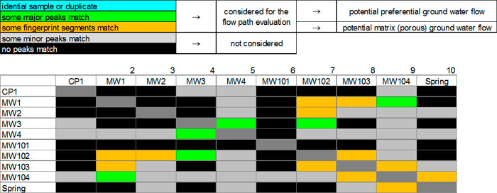
The BFA identified potential hydraulic connections between monitoring wells located on the site and between the site and third party off-site receptors, as indicated in Figure 11-14. BFA uses the fluorescent properties of the organic content of groundwater samples to develop well-specific fingerprints, which are subsequently compared to predict potential hydraulic connections. The potential hydraulic connections identified support the likely TCE migration pathways identified within the fractured bedrock CSM and demonstrate the complexity of the subsurface.

Figure 11-14. Background fluorescence analysis results.
Results–Source delineation
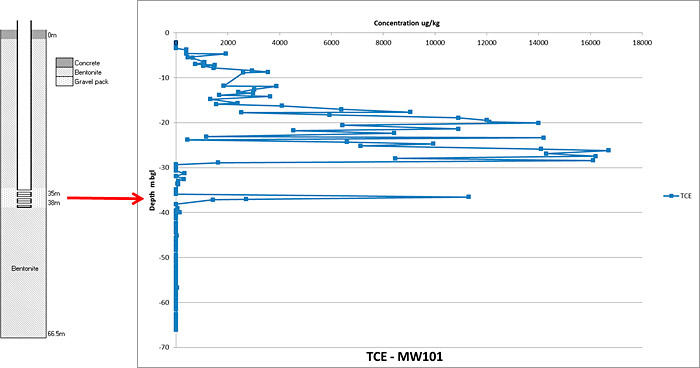
The use of Core DFN and analysis of rock samples using an on-site laboratory allowed the depths of TCE impact to be identified in near real-time. Rapid access to laboratory results informed decision making about drilling depth. Borehole drilling was then terminated once into ‘clean’ strata, reducing the operational drilling time spent on site. The first borehole drilled was advanced approximately 25 m into clean strata to confidently prove the maximum depth of impacts and this information was used to facilitate the earlier termination of subsequent monitoring wells, which were terminated less than 10 m into clean strata. In all cases, the base of the drilled boreholes was installed with a competent bentonite seal to prevent further downward contaminant migration and targeted monitoring wells were installed within contaminant transport zones (coincident with fractures). Figure 11-15 shows the vertical contaminant profile detected within the first borehole drilled, alongside the targeted monitoring well that was installed. In the case of this borehole, the decision was made to install a monitoring well targeting the high TCE concentrations detected at 37 m bgl, which corresponded with the location of a major fracture identified by the Core DFN and acoustic televiewer. The fractures with high concentrations located between 20-25 m bgl had also been targeted by an adjacent monitoring well installed during the preliminary site investigation in April 2015.

Figure 11-15. Vertical contaminant profile and targeted monitoring well installation.
During the HRSC investigation, a total of 351 Core DFN rock samples were collected from a total of 186.8 m of linear rock cores, across four borehole locations. All samples were analyzed on site for VOCs. To further assist in interpretation, samples were also analyzed for physical properties (porosity, % moisture, bulk density) allowing the calculation of porewater concentrations. Comparison of porewater concentrations with groundwater concentrations indicates that elevated concentrations of TCE are present within the groundwater and fracture network and are also present within the rock matrix.
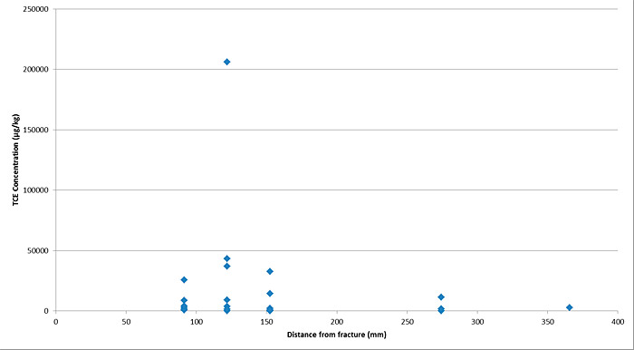
Of the 351 samples collected, the majority were collected from fracture surfaces and located either immediately above or below a fracture. Furthermore, 73 samples were collected within the rock matrix away from fractures and of these, 30 contained concentrations of TCE above the laboratory limit of detection (LOD). Assessment of the 30 matrix samples with detections above LOD against the distance of these samples from the fracture surfaces suggests that TCE impacts have diffused a maximum of 365 mm into the slate bedrock matrix. This information suggests that TCE contained within the rock matrix represents a potential secondary source of contamination. The implications of the secondary source is considered as part of the remedial options appraisal for the site. Concentrations of TCE as determined via Core DFN and sample distance from a fracture surface are plotted in Figure 11-16.

Figure 11-16. Plot showing TCE concentration in rock (µg/kg) vs distance of sample from fracture surface.
Outcomes and Challenges
The HRSC works used a complimentary set of techniques, bringing together multiple lines of evidence to produce a robust CSM. The HRSC techniques used also produced a high-quality data set within a brief time (drilling and laboratory mobilization of two weeks). The results of the characterization indicate the presence of TCE, both in the fractures and rock matrix, has informed the depth of impacts and provided information regarding the mechanisms for contaminant migration.
Data collected during the site characterization will be used to prepare a remedial options appraisal for the study site. Future remediation is likely to be challenging due to complex geology, depths of impact and presence of DNAPL. Pilot trials will be undertaken following the completion of the remedial options appraisal.
The collection of a large, robust data set has been used as the basis for technical discussions with local regulatory authorities, by demonstrating the complexity of the subsurface and has assisted in suggesting appropriate remedial end points in line with the UK risk based remedial framework. Positive feedback was received from the UK regulator regarding the works. HRSC assessment is to an extent an emerging technique in the UK and Europe and positive comments were received regarding the detailed approach to the investigation.
Lessons Learned
In the fractured bedrock setting, orientated information from downhole geophysics (optical or acoustic televiewers) allows full structural analysis beyond frequency plots and supports observations of fracture aperture. This is high-quality data that substantially improves the depth and breadth of the CSM and would also provide critical field data for any further numerical discrete feature network models.
The in-field Core DFN approach also allows site specific data to be gathered on the amount and nature of diffused contaminant vs contaminants in fracture groundwater. This is critical for the development of mass models, remedial options study and prognosis of long term rebound from back-diffusion. Remedial work undertaken on a site of the type described in this case study without the understanding gained from the Core DFN and structural data would have an extremely uncertain outcome, with a high risk of failure in the long term.


