6 Remediation Design
This chapter describes a framework for developing cleanup objectives and a remedial approach for contaminated fractured rock sites. The framework includes the essential elements necessary for effective, and adaptive, remedial decision making at these challenging sites. Figure 6-1 describes the framework for decision making (ITRC 2011), which is used to develop a CSM, set remedial performance objectives, and evaluate remedial options. The CSM is a living document that is refined throughout the process of developing and implementing a remedy, as well as during the subsequent performance monitoring. Using the CSM, absolute and functional objectives are developed to comply with applicable regulations and to establish metrics that are specific, measurable, applicable, relevant, and time-bound (SMART). Potential remedial technologies are described with a focus on key considerations for technology evaluation and selection in fractured rock. A screening matrix provided in this guidance (Table 6-2) helps the user select remedial technologies based on the characteristics of the fractured rock at a site. Once potential remedial technologies are identified, multiple alternatives can be developed to address contamination at fractured rock sites.
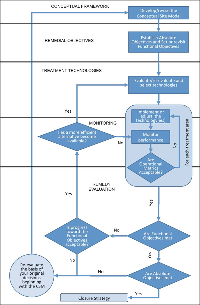
Figure 6-1. Remedial strategy development flow chart (ITRC 2011).
6.1 Remedial Objectives
A conventional objective of site restoration is to achieve prescribed cleanup levels such as MCLs for groundwater. Attaining low cleanup levels (such as drinking water standards) at fractured rock sites is often more challenging than at overburden sites, and may be technically or economically impracticable within reasonable time frames. Remedies can be developed, however, that address the most critical risks, foster partial cleanups, and address community concerns with more reasonable time frames and costs while continuing progress toward complete restoration in the long term. This approach is particularly applicable when distinguishing between source area and plume area remedial goals and remedies. Remedy implementation requires careful development of reasonable functional objectives for actions that may not meet the concentration-based criteria established in regulations, but that will provide benefits. These benefits include reduction in risk and contaminant mass flux, development of sites, and a transition to passive remedial options such as MNA, if appropriate.
The process for developing remedial objectives for fractured rock sites is similar to that for overburden sites. That process is described in detail in previous ITRC guidance (ITRC 2011), Chapter 3) and is only briefly summarized here. The primary difference for fractured rock is that the additional complexities and challenges of bedrock sites must be considered, particularly for development of functional objectives.
Absolute objectives are based upon broad societal values and upon state or federal regulations, such as protection of public health and the environment, protection of natural resources, and preservation of beneficial uses of groundwater. Functional objectives include steps or activities taken to achieve the absolute objectives. Functional objectives should conform to SMART attributes: specific, measurable, attainable, relevant, and time-bound (Doran 1981). A discussion of the reasoning for and development of SMART functional objectives is provided in previous ITRC guidance. Functional objectives are Remedial Action Objectives (RAOs), which are the objectives for a given set of actions, and can be interim or final. At many contaminated sites the functional objectives established for short-term actions do not represent final, or absolute, RAOs because the final RAOs often are not attainable in a reasonable time (less than 20 years or so).
Meeting all properly constructed and complete functional objectives should ensure that the absolute objectives are attainable. Examples of generic absolute and functional objectives for a contaminated fractured rock site are shown in Table 6-1. The generic absolute and functional objectives in Table 6-1 are not significantly different from those that might apply for unconsolidated media. More specific SMART functional objectives may be developed for fractured rock sites, as illustrated in the case example at the end of this chapter and with the discussion of remediation objectives as they relate to the monitoring strategy.
Table 6-1. Examples of possible generic objectives for contaminated fractured rock sites
| Absolute Objectives |
|---|
|
| Functional Objectives |
Risks
|
Extent
|
Longevity
|
Regulatory
|
Community
|
Land Use
|
Economic
|
Sustainability
|
Resource Conservation
|
6.2 Key Challenges for Remedial Design and Implementation
Although fractured bedrock remediation can present many challenges beyond those commonly encountered in overburden, three characteristics of fractured rock that present special additional challenges relative to overburden are:
- The wide spectrum of hydraulic transmissivities and contaminant mass storage domains that may be present, within even small portions of typical sites. Remedial technologies tend to be more commonly applied in domains characterized by higher transmissivity (secondary porosity features and larger fracture apertures), whereas in sedimentary rock, much of the contaminant mass may be present within less transmissive, primary porosity storage domains. Release or diffusion of contaminant mass from primary porosity storage domains occurs over a prolonged period (similar to back-diffusion in unconsolidated media), which affects remediation effectiveness and performance monitoring.
- Uncertainties that exist in groundwater flow patterns in fractured rock environments. Groundwater flow in fractured rock environments is generally subject to more uncertainty than in aquifers in unconsolidated media, which translates to greater characterization effort and cost and greater remediation effort and/cost, potentially without any significant improvement in overall site understanding.
- NAPL present in fractures has significantly less water interfacial area than in granular aquifers, and NAPL saturation (the amount of NAPL present relative to fracture volume) tends to be higher in less transmissive fractures. This condition generally reduces the effectiveness of remedial processes that rely on NAPL dissolution or on chemical and biological reaction.
6.3 Development of Remedial Strategies
Considering the characteristics and challenges of understanding fluid flow and contaminant fate and transport in fractured rock, remedial strategies that may be successful at unconsolidated media sites may not apply to fractured rock sites, or may require special additional design considerations to be effective. This section offers strategies for developing a remedial approach to fractured rock sites.
6.3.1 Focus on RAOs and Risk Reduction
Given the challenges associated with remediation in fractured rock, at some sites achieving absolute objectives or low prescriptive cleanup standards may not be realistic within a reasonable timeframe or cost, or due to technical limitations. Developing SMART functional objectives with a focus on risk reduction may be an appropriate strategy for these sites, while continuing progress toward complete restoration in the long term. Stakeholders should be engaged early in the remedial decision-making process at these sites. Important considerations include how a focus on risk reduction (rather than complete restoration) in the short-term affects community perception. Stakeholders should be informed about unremediated sources, long-term institutional controls, loss of resources, and property that will not return to beneficial use.
A receptor risk evaluation is a common component of a site investigation and is a critical component of assessing remedial options. Receptor risk evaluation is an ongoing process that continues through the life of a project. Groundwater discharge and vapor intrusion are two receptor risk components whose characteristics in fractured rock may be very different from that of overburden aquifers.
6.3.1.1.1 Groundwater Discharge
Groundwater from fractured rock aquifers may discharge to springs or other surface water bodies (wetlands, creeks, rivers, ponds, lakes), to potable wells located within or downgradient of a plume, or from abandoned mine openings. These discharges can affect receptors due to contaminant discharge and thus affect RAO development. The discharges also must be considered during remedial design. For example, the risk of discharge of a chemical reagent injected as part of a remedy must also be considered because in some cases groundwater flow in fractured rock aquifers may be fast, or discharge locations may be far from injection locations. Remedial goals and design should consider how the remedies will protect groundwater discharge areas and protect existing and future receptors.
6.3.1.1.2 Vapor Discharge
Vapor intrusion into overlying buildings may also occur from contaminated fractured rock. Vapor can be transmitted directly through vertical fractures or from fractured rock through overburden soil to the receptor. In settings with near-surface bedrock, buildings, utilities, and other structures may be constructed in direct contact with fractured rock. The potential for vapor intrusion and the rate at which it occurs can be greater in shallow bedrock, and migration endpoints may be less predictable compared to unconsolidated media (KDHE 2016). Evaluation and presence of a vapor pathway should be included in the CSM. Vapor pathways should also be considered during development of the RAOs, remedial design, and remedial action to understand how vapor risks may be affected, and to ensure that the selected remedy is protective and does not negatively affect receptors.
6.3.2 Address Contaminant Source Areas and Back-Diffusion
Source mass reduction, or mass flux reduction, may provide a realistic path forward with achievable goals, instead of attempting to treat the entire extent of contamination. A strategy focused on source treatment alone may not be sufficient where contamination has already migrated away from the source area and threatens human health or other sensitive downgradient receptors. The potential for matrix and back-diffusion should also be considered both within and downgradient of the source area. For example, sedimentary rock with significant primary porosity may also have a significant amount of contaminant mass contained in that primary porosity downgradient of the source area. As with sorbed-phase mass in the plume area at overburden sites, the contaminant may diffuse out of the primary porosity over an extended period of time, resulting in long-term plume persistence and continued risk even after source remediation is complete.
6.3.3 Acknowledge Uncertainty
Poor characterization and or invalid assumptions have historically led to failed remedies, a loss of resources, and costs to both the public and private sectors. A rigorous evaluation of uncertainty and the quality of the site characterization is therefore recommended when implementing a remedial strategy (ITRC 2012b). Consider if additional investment in site characterization may increase the probability of success for a remedy, or provide a return (in terms of lower cost) by providing more targeted or focused remedies. For example, if there is uncertainty that all source areas have been identified, then a source remedy may not be effective.
On the other hand, additional investment may not be necessary if the resulting data are unlikely to translate to a significant improvement in effectiveness or reduced cost of a remedy. For example, installation and testing of additional wells may allow a 3% to 5% reduction in uncertainty in aquifer transmissivity for a groundwater extraction system, but a small increase in pump rate may result in an effective remedy regardless of the uncertainty. Risk mitigation strategies that incorporate redundant or overly conservative assumptions and solutions due to uncertainties may increase cost and scope without providing any meaningful benefit. Thus, when making these decisions, acknowledge remaining uncertainties while developing a remedial strategy, and seek feedback while performing remediation that may further refine the CSM.
6.3.4 Develop a Contingency Plan
A contingency plan is another component of a successful strategy. While field pilot tests and careful design can reduce or eliminate the risk of poor remedial performance, developing a contingency plan in advance allows site managers to respond quickly to data that suggests a remedy is no longer performing as intended. The contingency plan should include an adaptive site management strategy that acknowledges uncertainties and outlines a plan to resolve and incorporate them as needed in additional characterization, optimization of an existing remedy, or transition to an alternative remedy.
6.4 Technologies for Remediation
This section provides general guidance for screening of remedial technologies to use in contaminated fractured rock. Screening can help in selecting an individual technology or combined technologies (spatially or temporally), or may be used to develop remedial alternatives. Remedial technologies are divided into three broad categories: physical removal technologies, containment technologies, and chemical/biological technologies. Substantial overlap can exist between among these categories and some technologies can fit in more than one category. A screening matrix that evaluates each technology considering rock types and characteristics (such as primary and secondary porosity or matrix storage) is provided in Section 6.4.1.2.
The CLU-IN website hosts a searchable database of fractured rock project profiles. This database is an additional resource for screening remedial technologies and accounts for rock types, location, and other characteristics.
6.4.1.1 Key Elements of the CSM Relevant to Technology Screening
Final selection, design, and deployment of remedial technologies considers all aspects of the CSM. At the technology screening level, key elements include the remedial strategy (Section 6.3), in addition to special considerations for bedrock lithology and contaminant characteristics.
Bedrock Lithology. Many site characteristics relevant to contaminant fate, transport, storage, and remediation are directly or indirectly related to the type of rock present and associated characteristics (see Table 2-1 and Chapter 4). Initial technology screening should therefore assess the general the bedrock lithology. Bedrock can be divided into sedimentary rocks and igneous or metamorphic rocks. Each of these can be further subdivided by their origin; for example, sedimentary rocks can be divided into clastics (such as sandstone or mudstone), or chemical (such as limestone or coal), whereas igneous rocks can be divided into intrusive or extrusive rocks, and metamorphic rocks into foliated or nonfoliated.
General lithology characteristics influence hydrologic and porosity characteristics. For example, a sedimentary rock such as sandstone may have a high primary matrix porosity whereas an igneous rock such as granite may not. Rock chemistry can also significantly affect geochemical conditions relevant for in situ chemical or biological remedies. For example, groundwater within a fractured limestone bedrock aquifer may have high alkalinity, which can impede a zero-valent iron remedy due to iron carbonate precipitation on the zero-valent iron particles. Similarly, a rock with elevated reduced iron content may be amenable to an abiotic degradation technology for chlorinated solvents.
Contaminant Characteristics. The contaminants of concern and their corresponding effects on fate and transport in the rock affect remedial technology screening. For example, contaminants that readily dissolve into groundwater may exhibit strong partitioning into the rock matrix by matrix diffusion and subsequent back-diffusion following attenuation or remediation of contamination within the secondary, or fracture, porosity. Contaminants present as NAPLs may be transported great distances at a site in which the rock exhibits a network of large, interconnected fractures. Similarly, the presence of organic carbon in the rock matrix (such as coal) may affect both sorption and transport of dissolved contaminants. Certain rock types exhibit properties that are amenable to natural attenuation through abiotic or biogeochemical transformation.
6.4.1.2 Technology Screening Matrix
Table 6-2 presents a screening matrix that identifies types of technologies that may apply at a bedrock site. Further discussion of each technology with emphasis on bedrock is provided in Section 6.4.2. Variations in bedrock physical, hydrologic, chemical properties, and time since release for NAPL at a site must be considered carefully during remedial technology selection. For example, at a granitic bedrock site with little primary porosity or matrix storage, but high secondary porosity, technologies such as pump and treat or an ISCO approach with a short-lived oxidant may be appropriate. In contrast, if a site has shale or sandstone bedrock with both appreciable primary porosity and matrix storage, then technologies or strategies with long-lived reagents or a thermal approach could be considered. This matrix is not intended to provide a site-specific solution, but rather to assist with an initial screening of technologies or combinations of technologies. Characteristics and remedial objectives must ultimately be evaluated on a site-specific basis.
Table 6-2 summarizes hydrology characteristics relevant to remedial screening and ranks their applicability as “high” (H) or “low” (L). The lower portion of Table 6-2 lists the applicability of technologies, and the presence or absence of contaminant mass as NAPL, in matrix storage, and matrix and fracture transmissivity.
The applicability of technologies to certain rock types and settings in Table 6-2 was assigned values of “Y” (yes), “N” (no), or “U” (unlikely). These values are intended as general guidance based on the professional judgment and experience of the ITRC team. A value of “N” or “U” should not be interpreted as a conclusion that a technology cannot or should not be applied at a site with the associated characteristics. Ultimately, that decision must be based upon site-specific characteristics, remedial strategies, and objectives. In addition, innovations in design can advance technologies for successful applications at sites that do not currently seem to be good candidates for those technologies.
Table 6-2. Remediation technology screening matrix for fractured bedrock environments.
Click Here to view Table 6-2 in Adobe Acrobat format.
6.4.2 Remediation Technologies for Bedrock
General types of technologies are discussed in this section, with an emphasis on special characteristics or considerations for design and implementation in bedrock. The CLU-in website includes bedrock remediation case studies, organized by remedial technologies. The CLU-in site also includes a database of fractured bedrock project profiles that is searchable by both remedial technologies and keywords.
6.4.2.1 Physical Removal Technologies
Physical removal technologies are those that recover contaminants from bedrock. These technologies range from direct physical removal methods such as excavation, to indirect removal methods such as multiphase extraction and thermal treatment (which rely on physical properties of the contaminant, such as volatility, for removal). Physical removal technologies are more commonly applied to source areas due to technical feasibility and cost considerations.
Removal ▼Read more
Thermal Remediation Methods ▼Read more
Air Sparging ▼Read more
Vapor and Multiphase Extraction ▼Read more
Surfactant/Cosolvent Flushing ▼Read more
LNAPL Recovery ▼Read more
6.4.2.2 Containment Technologies
Containment technologies prevent or reduce contaminant mass flux and migration. Containment technologies offer little or no direct treatment of concentrated source areas, but instead protect downgradient receptors. Groundwater pump and treat systems are historically the most commonly deployed bedrock containment technology. Permeable reactive treatment zones are another containment technology used in fractured bedrock.
Groundwater Pump and Treat ▼Read more
Permeable Reactive Barrier Zones ▼Read more
6.4.2.3 Chemical and Biological Technologies
Chemical and biological technologies remediate contamination by transformative and destructive processes such as in situ chemical oxidation (ISCO), in situ chemical reduction (ISCR), in situ bioremediation (ISB), and various combinations of these technologies. As when using these technologies in porous media aquifers, the contaminant properties, geochemistry, rock matrix properties, and presence of organics and inorganics in the matrix are important factors in remedy selection and design. Formation hydraulics, mineralogy, primary and secondary porosity, matrix storage, and fracture aperture size are considerations specific to fractured bedrock remediation for in situ technologies. For NAPL treatment, an additional challenge is that the NAPL-water interfacial area (which is exposed to reaction with chemical reagents and to microbial processes) is substantially lower than in granular porous media aquifers, and a greater proportion of the NAPL may be trapped in less transmissive fractures (Schaefer 2016). This condition can significantly reduce overall treatment effectiveness.
Selecting specific amendments at a site requires expertise and is beyond the scope of this guidance; however, general observations that are relevant at the technology screening level are presented.
In Situ Chemical Oxidation and In Situ Chemical Reduction ▼Read more
Monitored Natural Attenuation ▼Read more
6.4.2.4 Innovative and Combined Remedies
Contaminated fractured bedrock sites often present a unique set of site conditions that require development or modification of typical remedial approaches. Innovative technologies, such as electrokinetic remediation, may offer special advantages in fractured rock settings. Coupling multiple technologies customizes remedies to address the wide range of conditions present at typical hazardous waste sites. Technologies can be coupled in time (one technology followed by another technology in the same treatment area), space (different technologies applied simultaneously in different parts of the site), or both.
Certain combinations of technologies, for example ISCO with ISB, or ISCO with ISCR, were historically considered incompatible with each other. Recently, however, integration of multiple technologies (including technologies historically considered incompatible) has been found to provide yield synergistic benefits for effective site remediation (ITRC 2011). For example, ISCO and ISCR have been applied successfully in different portions of a fractured bedrock site impacted with DNAPL (see the Former Industrial Site case study). As another example, the biogeochemical reductive dechlorination (BiRD) process can be combined with ISB to stimulate microbial reduction of native iron and formation of reactive iron sulfide minerals. These reactive minerals are capable of abiotic reaction and destruction of contaminants such as certain chlorinated VOCs. As with coupled technology applications in overburden (ITRC 2011), combined technology remedial designs for bedrock must account for the potential interactions of the different technologies in time and space.
6.4.2.5 Bench and Field Pilot Test Considerations
Bench and field pilot tests can provide important, site-specific information for remedy evaluation and design. Contaminant treatability, rock-chemistry interactions, reagent distribution, long-term treatment prospects, and overall effectiveness at a field-scale for a technology in a fractured rock aquifer may be different than in overburden. Several case studies offer examples of how bench and field pilot tests have been performed for a variety of site conditions. Bench and field pilot tests for fractured rock sites have two key considerations that differ from granular overburden sites: rock surface area and reagent transport.
Rock Surface Area
The rock surface area exposed to groundwater, contaminants, and reagents is different in fractured rock relative to overburden, and is important for all stages, from bench test to full-scale implementation. Bench testing for remediation technologies that are strongly influenced by interaction with particle surfaces (such as chemical and biological technologies) must account for this difference. For example, bench tests of oxidant demand or pH buffering of a relatively short-lived reagent in a fractured granite rock with little or no primary porosity should analyze the reagent solutions only in contact with natural fracture surfaces. One method to restrict reactions to only fracture surfaces is to coat the “cut” surfaces of rock cores with epoxy or other nonreactive material and immerse the fracture face in the solution under evaluation. These tests should not be conducted with crushed rock samples, or with core segments in which portions of the drilled surface of the core (as opposed to just the natural fracture surfaces) are exposed to the reagents. Using crushed rock or drill core surfaces exposes fresh, unweathered mineral surfaces to the reagents, which would not normally occur in field conditions.
Reagent Transport
Fracture-controlled groundwater flow in bedrock can be much faster than typically observed in overburden aquifers. This factor must be considered when evaluating remedial technologies, and especially when evaluating technologies that rely on fluid flow, such as injection of a soluble chemical or biological reagent. The much smaller rock surface area exposed to reagent interaction in bedrock aquifers relative to granular overburden aquifers strongly affects characteristics such as oxidant demand and pH shifts. This reduced surface area is significant for technologies such as in situ chemical and biological methods, which require injection of a reactive reagent. The differences in reactivity associated with surface area also affect reagent transport. The reduced surface area exposed to reaction may translate to less degradation or reaction of a reagent, which therefore results in increased reagent transport. This result must be considered for the following reasons:
- Injected reagents may be transported far greater distances and in far shorter time frames in fractured bedrock aquifers than in granular overburden aquifers. At sites where groundwater discharges to surface water (by springs, for example) or other receptors, the risk of reagent discharge must be evaluated.
- Transport of liquid reagents preferentially follows transmissive fracture networks. At many sites, the contaminant mass and flux are lowest and reagent transport is greatest in the most transmissive zones. Thus, a liquid reagent injection may initially exhibit a large radius of influence and effective reductions in groundwater contaminant concentration or flux. But at sites with high primary porosity, the contaminant reductions may be short-lived due to mass flux from less transmissive zones, primary porosity, or matrix storage domains.
- Transport of nonaqueous liquid reagents (such as vegetable oils) or of aqueous solutions with high concentrations of dissolved solutes (all of which affect viscosity and density) may also be different in fractured rock. These fluids exhibit a greater tendency to float or to sink within fracture networks due to the contrast in density and the greater size of fracture aperture relative to intergranular pore throat diameter.
- Dilution characteristics of injected reagents in fractured bedrock may be different from typical overburden sites. For example, reagents may be diluted due to distribution over larger radii of influence, or could be concentrated at greater distances due to flow in relatively small but very transmissive fractures.
6.5 Case Example
The Former Industrial Site in Greenville, South Carolina, provides a case study for the remedy selection process. Further details regarding the site conditions, remedial actions, and results are provided in the full case study. In summary, an estimated 1,365 gallons of trichloroethene (TCE) were released to the environment at the site between approximately 1991 and 1996. The source area lies near the top of a hill and the groundwater plume in the saprolite and bedrock occupies approximately 15 acres. Groundwater is naturally relatively acidic (pH approximately 5.2), thus there is little biodegradation occurring. The resulting groundwater plume in saprolite overburden and bedrock is approximately 15 acres. The bedrock is a foliated schist and gneiss metamorphic rock, with discrete relatively horizontal, transmissive fracture sets, and low primary porosity or matrix storage.
6.5.1 Objectives
This example site illustrates how difficult, yet important, it is to define the absolute objectives and associated SMART functional objectives for remediation of the site.
6.5.1.1 Site Risks
A potential risk to human health at this site is vapor intrusion into the building adjacent to the source area (Figure 6-2). Piping and appurtenances related to TCE use at the facility were removed. Unsaturated soil in the source area was previously remediated by a combination of soil removal, soil vapor extraction, and in situ thermal desorption. Results of subsequent vapor sampling inside the building yielded initial cancer screening risks well below the 1.0 x 10⁻⁶ threshold, thus there is no unacceptable risk to workers. TCE and cis-1, 2-dichloroethene migrated off site in groundwater, but no residences or other actively occupied buildings overly the plume and groundwater is not used. Groundwater flows towards a local river adjacent to the site.
The responsible party no longer owns the property but retains liability for the remediation. The building is currently used as a warehouse and for light industrial purposes. The primary driver for site remediation is the off-site migration of impacted groundwater and potential discharge to the local river. The goal of the responsible party is to remediate the site groundwater to MCLs within 15 years to eliminate their ongoing liability in a reasonable timeframe.
6.5.1.2 Absolute and SMART Functional Objectives
The absolute objectives for the site were established as the following:
- Protect human health and the environment.
- Mitigate off-site migration of contaminants and potential impact to surface and groundwater resources.
The site investigation demonstrates the following:
- High concentration and likely DNAPL in the aquifer in the source zone provide an ongoing TCE source to groundwater.
- TCE and degradation products in the plume zone (groundwater and sorbed) result in off-site migration and potential discharge to a surface water body.
Although high TCE concentrations are in the source area groundwater, the aquifer is approximately 55 feet below grade in the source area and the saprolitic soil has low permeability, which helps mitigate vapor risks. Vapor sampling inside the building confirmed the absence of vapor risks to workers.
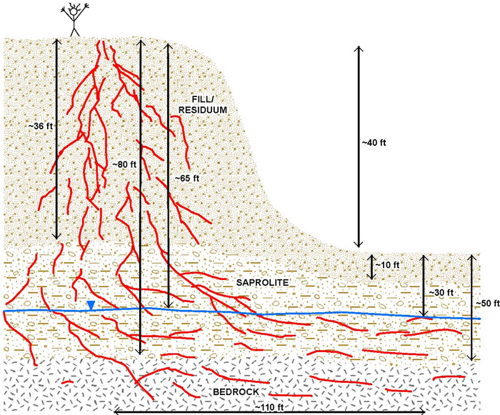
Figure 6-2. Cross-sectional schematic illustrating potential pathways and risks at the Former Industrial Site, consistent with the 21-Compartment Model in Table 6-4.
Table 6-3. Absolute and functional objectives and SMART attributes for Former
Industrial Site.
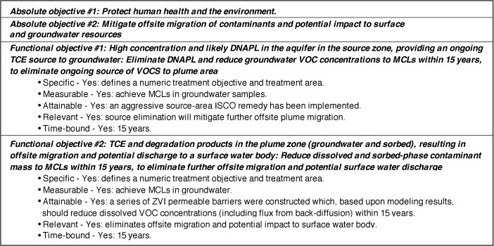
Table 6-3 lists the absolute and functional objectives, along with a list of the SMART attributes of each functional objective. In this case, the vadose zone was addressed with previous remedial actions, and only saturated-zone impacts in the source and plume zones remain. The responsible party identified a specific and time-bound objective of MCLs within 15 years. Modeling results predicted that a remedy that rapidly eliminated mass flux from the source zone would not be sufficient (by itself) to collapse the plume zone within 15 years, thus both source-zone and plume-zone active remedies were required.
The modeling results were then used to develop a design that coupled an ISCO remedy in the source zone with a series of three ZVI permeable reactive barriers in the plume area. Modeling results based upon the assumption that groundwater passing through each barrier was reduced to MCLs (leaving back-diffusion of VOCs from the sorbed phase as the remaining source to plume-zone groundwater) provided predictions of long-term trends in groundwater VOC concentrations. As part of the performance and remedial progress evaluation, long-term groundwater monitoring results can be compared to these predicted trends to ensure that progress is being made towards the functional objectives. This comparison provided a SMART basis to evaluate remedy progress and to reevaluate the CSM and remedy.
6.5.2 Technology Screening
The bedrock at the site is characterized as metamorphosed schist and gneiss, with relatively low primary porosity or matrix storage. Saprolite and partially weathered rock also requires treatment, which influenced remedy selection but is not detaileded in this example. Although DNAPL is not observed in bedrock, elevated TCE concentrations indicate that a DNAPL phase is likely present. A plume of over 900 feet has emerged from the source area. Table 6-4 summarizes the initial screening of remedial technologies for the site based upon the type of bedrock present.
Table 6-4. Remediation technology screening matrix for fractured rock environments.
Click Here to view Table 6-4 in Adobe Acrobat format.
Technologies were selected on the following basis:
- Among likely applicable physical technologies, air sparging was eliminated due to the need for extensive infrastructure construction (because much of the plume area extended off site with limited access), and surfactant flushing was eliminated because a separate phase DNAPL was never found in the fractured bedrock.
- Among chemical/biological technologies, in situ bioremediation and monitored natural attenuation were eliminated due to relatively acidic groundwater conditions (pH approximately 5.2). Very little natural degradation of TCE was occurring, and estimates of pH buffering requirements to bring pH within a reasonable range were impractical.
- Among ISCO and ISCR technologies, methods with long-lived reagents were desirable because the client no longer owned the facility, and access was limited.
Based on these considerations, ISCO and ISCR technologies with long-lived reagents were retained for detailed consideration.
6.5.3 Technology Selection
The technologies selected from screening-level assessment were ISCO and ISCR technologies using long-lived reagents. Conceptual modeling with REMChlor and PREMChlor was used for both the overburden and bedrock to assess the technology-independent remedial performance required to achieve the functional objectives. This effort indicated that the functional objectives could be achieved if:
- The source area was rapidly eliminated with an aggressive technology.
- Permeable treatment zones were constructed at accessible locations within the plume so that groundwater migrating through the barriers was treated to below MCLs. VOCs would diffuse (from matrix porosity and from the overlying saturated overburden) into groundwater, which would then encounter subsequent barriers.
Permanganate ISCO was selected for the source area. The permanganate was delivered with a solid slurry injection method. Injection in the bedrock interval targeted the existing fracture network. Transmissive, water-bearing fracture zones were identified by coring at each injection location. The following factors influenced remedy selection:
- Large amounts (tons) of permanganate can be injected in a short period of time. The large volume was required to satisfy the natural oxidant demand as well as provide a slowly dissolving, long-lasting (years) source of oxidant to groundwater.
- Permanganate exhibits a long lifetime in groundwater and can diffuse vertically from each lens to address the full range of fracture and matrix porosity. In fractured rock, permanganate can diffuse into the matrix porosity like the pathways followed by VOCs.
ISCR with ZVI was selected for the plume area. The ZVI was injected as a solid slurry. ZVI was selected rather than permanganate for the plume area because groundwater may discharge to an adjacent surface water body. The combination of technologies (ISCO in the source area with simultaneous application of ISCR in the downgradient plume area) required quantitative considerations of reagent transport, particularly of permanganate from the source area to the down gradient ZVI treatment zones.
- A granular (rather than micro- or nanoscale) ZVI product was used because the granular ZVI would remain active for a long period of time (many years).
- The long-lasting ZVI provides long-term treatment of VOCs desorbing and diffusing into groundwater from the rock matrix or from the overburden.
The approach used a wide variety of site characterization tools prior to remedial design. The remedial design included quantitative modeling coupled with bench and field pilot tests to confirm key assumptions. The full-scale implementation adopted a flexible approach that began with a design based on the CSM and available data, but was optimized on a boring-by-boring basis as core data and field observations became available.

