• Skip to main content
itrc_logo

Characterization and Remediation of Fractured Rock

Home
About ITRC
Navigating this Website
1 Introduction
1 Introduction Overview
1.1 Characterizing Fractured Rock
1.2 Comparing Unconsolidated Porous Media CSMs and Fractured Rock CSMs
1.3 21- Compartment Model
1.4 Value of Investigation
2 Geology
2 Geology Overview
2.1 Elements of Terrane Analysis
2.2 Benefits of Terrane Information for the Initial CSM
2.3 Terrane Analysis Case Study
2.4 Terrane Analysis Summary
3 Hydrology
3 Hydrology: Fluid Flow Overview
3.1 Fractured Rock Characteristics
3.2 Fluid Dynamics
3.3 Vapors in Fractured Rock
3.4 Role of Scale in Fractured Rock Fluid Flow
4 Chemistry
4 Chemistry: Fate and Transport Overview
4.1 Fate and Transport Mechanisms
4.2 Contaminant Properties Affecting Fate and Transport
5 Site Characterization
5 Site Characterization Overview
5.1 Review and Refine Existing CSM
5.2 Define the Problem
5.3 Identify Significant Data Gaps
5.4 Define Data Collection Objectives and Design Data Collection Process
5.5 Select Investigation Tools
5.6 Develop and Implement Work Plan
5.7 Manage, Interpret, and Present Data
5.8 Lessons Learned
6 Remediation Design
7 Monitoring
8 Modeling Fractured Rock
9 Stakeholder Perspectives
10 Regulatory Challenges
11 Case Studies
11 Case Studies Overview
11.1 Former Industrial Site, Greenville, South Carolina
11.2 Solvents Recovery Service of New England, Inc., Superfund Site, Southington, Connecticut
11.3 Characterization of Fractured Bedrock, United Kingdom
Appendix A. Karst Terranes
Appendix B. Bedrock Types
Appendix C. Drilling
Appendix D. The 21-Compartment Model
Additional Information
Glossary
References
Acronyms
Acknowledgments
Team Contacts
Document Feedback


Characterization and Remediation in Fractured Rocks
HOME

5.4 Define Data Collection Objectives and Design Data Collection Process

Once the data gaps are identified, investigators can establish specific data collection objectives and design the data collection process. Data collection objectives are used to determine specific data needs and to select tools and techniques to be used in the investigation. This section describes data collection objectives common to many fractured rock sites, as well as the design of the data collection process and key factors that should be considered in the characterization planning.

5.4.1 Establish Data Collection Objectives

Once the significant data gaps are identified, specific data collection objectives can be established. A more detailed discussion on data collection objectives is included in Integrated DNAPL Site Strategy (ITRC 2011) and Integrated DNAPL Site Characterization and Tool Selection (ITRC 2015b). The data collection objectives depend on the purpose and stage of the characterization. For example, the data collection objectives developed as part of a remedial investigation may differ from those developed for assessing the effectiveness of remedial alternatives.

Data collection objectives should be clear, focused, and specific. Objectives should account for factors such as fracture orientation, spacing and aperture, hydraulic head, and flow velocity. These characteristics define the type of data needed, the data density and spatial resolution, and measurement and analytical resolution. As these objectives become more focused, they help to determine the type of data quality (quantitative, semiquantitative, or qualitative) required to meet the data collection objective and thus the appropriate investigative tools.

The fourth significant data gap noted in Table 5-1 is: the rate at which the deepest and farthest contamination is moving. Based outcrop mapping and available structural maps, a number of fractures, or other planar features, are oriented toward down gradient water supply wells. However, VOC data collected from a deep-water supply well indicate contamination is sidegradient to the assumed flow direction. The data collection objectives in this situation may be as follows:

  1. Document the orientation of fractures sets in the subsurface to the base of the deepest screened water supply well.
  2. Define the interconnectivity of fractures.
  3. Measure the flow velocities in discrete borehole intervals.
  4. Calculate the groundwater gradient between the source area and water supply wells.

Another example of a significant data gap, with corresponding specific characterization and data collection objectives, is presented below:

Significant Data Gap: The vertical and lateral extent of dissolved phase contamination is unknown.

Characterization Objective: Determine the lateral and vertical extent of dissolved phase VOCs.

Data Collection Objective: Gather data, including fracture location, orientation, connectivity, and VOC concentration in areas beneath the source and between the source and the water supply wells.

The data characterization process is shown in Figure 4-1 of the DNAPL site characterization guidance (ITRC 2015b).

5.4.2 Design Data Collection Process

After establishing the data collection objectives, the next step is to design the data collection process. Designing or developing this process begins before the selection of investigation tools, and is an integral and iterative process within the selection of investigation tools. The design includes sequencing and planning characterization activities. Additionally, the process is optimized to ensure representative data, identify cost-effective approaches, and prevent the spread of contamination during the investigation activities. The sequencing and approach developed from this process should be incorporated into the project work plan.

In general, the data collection process should begin with available data and data obtained through nonintrusive evaluations. These findings can then be used to plan intrusive measures (such as boreholes) if needed. Thus, the initial steps should include the components of the terrane analysis that use available resources and techniques, such as: topographic and geologic maps, light detection and ranging imagery (LiDAR), and aerial photography, to conduct activities such as lineament analyses and initial cross-sections construction. Minimally intrusive or nonintrusive field activities should follow, including surface reconnaissance techniques (such as mapping, outcrop analyses, and measurements) and surface geophysical surveys (such as ground penetrating radar and electrical resistivity).

These results may indicate the need for intrusive methods. For fractured rock characterization, subsurface data are collected using existing boreholes and wells, or a borehole or well installation program to supplement the existing data. The number and locations of data points may be selected subjectively at first, but several approaches can bring objectivity to the selection process. In selecting subsurface data collection locations, first consider how the general structure, or fabric, of the terrane and fracture orientations may affect groundwater flow and contaminant migration.

An example of selecting fractured rock (Appendix C) locations is presented in Figure 5-1. After reviewing available site information, potential source area locations may be mapped and initial investigative borehole locations can be selected. This decision may differ between boreholes drilled in unconsolidated deposits versus those that may need to be drilled in fractured rock, as illustrated. The general regional bedrock structural fabric (strike and dip) is considered, and the array of bedrock drilling locations can be rotated toward the structural fabric orientation, with the amount of rotation determined by the dip angle of the fabric. Generally, there is no rotation with horizontal or subhorizontal dip, and more rotation with steeper dips. In general, the middle of the downgradient monitoring well array should be within the acute angle defined by the estimated hydraulic gradient direction and a line drawn parallel to the dipping regional bedrock structural fabric through the interpreted source.

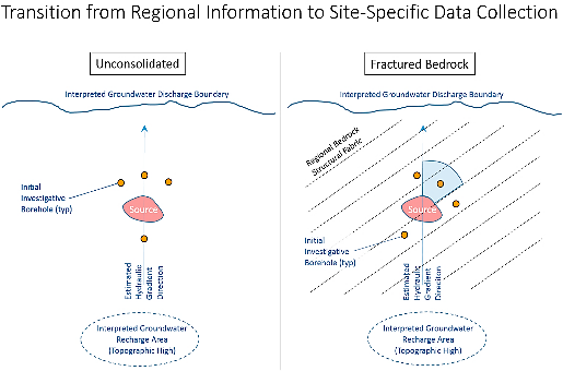
Figure 5‑1. Selection of Initial Fractured rock Drilling Locations

The number and locations of data collection points needed cannot be predicted. Investigators should consider the number, type and amount of data required as part of the next field investigation to further refine the CSM. After several iterations of this process of data collection and evaluation, the number and locations of data become adequate to support informed decision-making, the significant data gaps are resolved, and the CSM is refined. The most recently collected data might not materially change the CSM, which indicates that the CSM may be adequate for future decision making. Judgments regarding data adequacy in terms of number and location are usually qualitative, may involve many stakeholders, and depend on the characterization objectives for the given stage of the project.

The factors listed below should be considered when designing a data collection process, selecting characterization tools, and developing the overall approach and sequencing of the process.

Using existing wells or boreholes with long open intervals ▼Read more

Early in the development of the subsurface investigation program, consider if the site already has existing wells (such as production wells or old monitoring wells) or boreholes, which may be used or retrofitted as data collection wells for future site characterization and monitoring. Note that wells with long open or screened intervals could detrimentally affect site conditions. Data collected from these wells may have limited value without further borehole characterization or modification for multizone isolation (for instance, installing packer strings to preserve the opportunity for future zone-specific vertical profiling, multizone testing, or interval-specific remediation). Production wells in bedrock often are drilled to whatever terminal depth is required to achieve the desired well yield—hundreds of feet in some cases—and commonly are completed with long, open boreholes. Preexisting supply wells or boreholes with long open intervals may have exacerbated subsurface contamination and may still affect groundwater by allowing cross-contamination between discrete water-bearing zones that would otherwise have limited hydraulic interconnection. Hydraulic head data and groundwater samples collected from wells with long open intervals are of limited value for characterization because the resulting information is a composite of each interval and cannot be ascribed to any particular depth within the formation.

Preexisting wells or boreholes with long open intervals may need to be grouted and decommissioned or converted to monitoring points early in the site characterization process. Contaminants may have been mobilized into former pumping wells and in some cases, deep bedrock production wells that have been repurposed for waste disposal. These wells may be key locations for site characterization and monitoring and should be strongly considered for retrofitting as monitoring points. Often, the diameters of supply wells are large enough to fit multiple monitoring wells with screens and sand packs at multiple depths, separated by appropriate borehole seal materials (such as bentonite or grout). Alternatively, multiport wells/sampling devices can be installed at specified depth intervals. Prior to selecting permanent monitoring depths, however, the borehole should be characterized using downhole methods, depth-discrete sampling, or both to identify predominant flow zones and their specific chemical signatures or fluxes interval. This evaluation should include a borehole geophysical logging program.

Strategies for borehole/well installation programs ▼Read more

General factors to consider when designing a drilling program in fractured rock include:

  • Bedrock evaluations typically require more money and time per data element than investigations performed in unconsolidated media. Consequently, using a conventional phased approach or an adaptive approach, especially when the CSM is uncertain (such as in the early stage of an investigation, in an area with little prior characterization, or in structurally complex systems) can help optimize the characterization efforts.
  • Data collected during the drilling of a borehole (with a permanent well or monitoring device) are often as important as data collected from a completed monitoring well. For example, in situ fracture orientation data, which are crucial for evaluating likely fluid-flow directions, must be collected from boreholes before installing monitoring wells and other monitoring systems.
  • The basis for a potential depth limit for the investigation should be defined for each phase of work; this basis may change between phases of work as the CSM is developed. A depth limit may be set based on the current understanding of bedrock stratigraphy (for example, encountering a certain recognized regional aquitard) or data collected while drilling (for example, vertical profiling of contaminant concentrations in screening-level groundwater samples, hydraulic conductivity, or both).

See Appendix C for more specific guidelines for drilling programs and drilling techniques.

Precautions and management of long open boreholes during a drilling program ▼Read more

Long open intervals in bedrock provide ambiguous data and can act as conduits for cross-contamination between water-bearing zones. According to Sterling (Sterling 2005):

Rock-core analyses, combined with the other types of borehole information, show that nearly all of this deep contamination was due to the lingering effects of the downward flow of dissolved TCE from shallower depths during the few days of open-hole conditions that existed prior to installation of the multilevel system.

This study concluded that the lingering impacts of borehole short-circuiting can be particularly persistent in rocks with significant matrix porosity, due to matrix-diffusion effects. Thus, it is important to plan, collect, and interpret data quickly during the drilling process. Working quickly allows monitoring intervals to be selected rapidly and the borehole completed or packed and isolated as quickly as practicable after drilling.

Some approaches to reduce cross-contamination during borehole advancement include:

  • Use fresh, potable water to flush rock cuttings, collecting the water and disposing of it, (after treatment if needed), rather than recirculating the water. Similarly, using air-rotary or air-hammer drilling can be considered for situations when it is not necessary to collect rock core.
  • Install temporary packers (such as inflatable packers or K-packers) or FLUTe liner in boreholes when not drilling.
  • Drill with mud to form a mud cake on the borehole wall to limit exfiltration of fluids from the borehole into formation. Be careful to avoid plugging or reducing permeability in fractures intersecting the borehole; synthetic drilling muds that can be decomposed after drilling may be appropriate here.
  • Drill using the dual-wall reverse-circulation drilling technique. In this technique, the drilling fluid (water, drilling mud, or air) is circulated downward between the outer and inner casings of the drill string. The drill cuttings and the drilling fluid enter openings on the drill bit, which is attached to the inner casing (the drilling rods) and circulate upward within the inner casing to the surface. The outer casing, which advances as drilling progresses, can help reduce the potential for cross-contamination within the borehole.
  • Install intermediate casings during borehole advancement to isolate the shallower, potentially impacted intervals from the borehole prior to drilling deeper. Multiple casings can be installed at one location, if necessary, although the initial borehole diameter limits the number of intermediate casings that can be installed.

DNAPL contingency planning ▼Read more

DNAPL that is pulled down through incomplete boreholes can contaminate deeper, previously clean bedrock zones. When drilling at a site that may have DNAPL in the subsurface, have a plan to recognize DNAPL and avoid drilling deeper if it is encountered. Watch drilling fluids, rock cuttings, and core samples for an oily appearance or sheen and monitor VOC concentrations with a photoionization detector (PID) or similar instrument. If an oily appearance or sheen is observed, or there is a substantial increase in VOC readings, stop drilling and evaluate whether pooled DNAPL (which is potentially mobile) is present. Check the bottom of the borehole for pooled DNAPL using an interface probe or bottom-loading bailer. If pooled DNAPL is not encountered and if the drilling method uses recirculated drilling fluids (such as mud rotary drilling), the drilling fluids should be replaced with clean water before drilling deeper. Replacing the drilling fluids reduces the potential for cross-contamination and makes it easier to see a new sheen encountered at a deeper interval.

Accumulated DNAPL in the bottom of the borehole, however, indicates pooled DNAPL. If DNAPL has accumulated, remove it using a bottom-loading bailer or pump. Then, grout the borehole or quickly install a DNAPL monitoring well equipped with a sump below the screen. Fill the annular space surrounding the sump with grout.

Sometimes, a discrete fracture or interval of fractures can be identified in the borehole where the DNAPL was encountered. For example, if a rock core indicates the rock is generally unfractured, competent, and has little matrix porosity, yet there is a discrete fracture or zone of fractures within the core that indicates DNAPL presence (such as visible NAPL, sheen, staining, elevated PID readings), this fracture may be the NAPL-bearing fracture. If there is a sufficiently long interval (at least several feet) of competent, unfractured rock with low matrix porosity below this fracture, an intermediate casing can be set in the borehole to isolate the DNAPL-bearing fracture from the borehole, and thus allow deeper drilling. If an intermediate casing is set, after the grout is cured the drilling fluid should be replaced and the casing should be flushed with clean water. The water flushed from the borehole should be observed and monitored for indications of residual DNAPL. When the borehole is advanced again, the same DNAPL monitoring should continue.

In addition to the contingency planning at individual drilling locations, the sequence of borehole locations can be used to reduce the potential for cross-contamination. If practical, first assess the bedrock system at locations that are expected to be uncontaminated or contain only low levels of contamination before drilling in highly contaminated areas. Findings from these less-contaminated areas will improve planning to minimize cross-contamination when drilling in more contaminated areas (working from the outside to the inside, clean to dirty).

Data collection during borehole advancement ▼Read more

The following data should be collected as a borehole is being advanced, if applicable to the selected drilling methodology:

  • drilling rates (minutes per foot, and changes in rates), which indicate the general competency of the bedrock
  • water production (air rotary or mud/water rotary drilling) or loss (mud/water rotary drilling), which indicates the approximate first encounter of relatively permeable zones
  • rock quality designation (RQD), which is semiquantitative, measures the competency of the rock, and is inversely related to the degree of fracturing.

RQD (each core run) = [sum of lengths of rock pieces 4 inches (10 cm) or longer]

[total core run length]

The lengths of rock pieces are measured along the centerline of the core sample. Rock quality can then be described as follows:

Table 5‑2. Rock quality designations (QJEG 2007)

RQD Rock Mass Quality
<25% completely weathered rock
25-50% weathered rock
50-75% moderately weathered rock
75-90% Hard rock
90-100% fresh rock

▼Read more

  • indications of contamination (visual, olfactory, PID) in drilling fluid, rock cuttings, or rock core samples
  • core sample inspection data: lithology, stratigraphy, fracture orientations, identification of fracture sets, indications of weathering/staining from groundwater flow, fracture infilling, indications of contamination, and other indications as appropriate
  • rock core sampling for laboratory analysis of rock matrix parameters (such as porosity, bulk density, total organic carbon, and contaminant concentrations)
  • cuttings: lithology, indications of contamination
  • water levels in adjacent wells, preferably through continuous monitoring using data logging pressure transducers, which provide inexpensive data regarding connectivity between existing and new boreholes
  • single-packer testing of the newest drilled borehole interval, for hydraulic conductivity profiling and, if water is extracted rather than injected, collection of screening-level groundwater samples

Data collection after borehole drilling, prior to well or casing installation ▼Read more

The following data should be collected once borehole drilling is complete, but before a well is installed in the borehole or before installing an intermediate casing across an interval of a borehole:

  • dual-packer (straddle packer) testing of borehole intervals, for hydraulic conductivity profiling of discrete borehole intervals and, if water is extracted rather than injected, collection of screening-level groundwater samples
  • borehole geophysics, particularly optical or acoustic televiewer for measurement of the orientations and spacing of in situ bedrock fractures, and other borehole geophysical tools/methods, to log lithologic changes and other rock properties; see Tools Selection Worksheet and USGS “Geophysical Toolbox” (Day-Lewis 2016)
  • heat-pulse flowmeter, with and without in-well pumping, to identify transmissive fractures and potential in-flow and out-flow zones intervals
  • transmissivity profiling to identify transmissive fractures and borehole intervals
  • NAPL/FACT FLUTe, to identify specific depth intervals of NAPL or dissolved phase concentrations possibly indicative of NAPL in contact with the borehole wall
  • borehole tracer tests

Borehole Completion ▼Read more

Considering the data collection objectives, use the data collected from each borehole to select target intervals for monitoring well completion (screen or open-rock), or multiple target intervals for a multilevel monitoring system. If the monitoring system will not be installed soon after borehole drilling and testing, minimize the potential for cross-contamination from the borehole using temporary packers, a FLUTe® liner, or other appropriate methods.

Characterization of uppermost bedrock ▼Read more

Often, the uppermost bedrock (positioned either directly below unconsolidated deposits or exposed at the ground surface) may be more weathered and fractured, or may contain fractures of larger aperture than more competent, underlying rock. As a result, the uppermost rock may have significantly different hydrogeologic characteristics and broader contaminant distribution than the deeper bedrock. In some cases, much of the contaminant mass resides in the upper weathered bedrock interval.

A well-designed bedrock characterization program accounts for this upper contaminant mass and includes provisions to characterize this interval. In some jurisdictions, well drilling regulations can require that as much as 10 to 20 feet of the upper bedrock that underlies the unconsolidated deposits be cased off before advancing the borehole deeper into bedrock to prevent cross-contamination. This potentially significant interval may not have been characterized at some sites during the initial phases of an investigation. Examples of activities to assess the upper bedrock before it is permanently cased off include:

  • setting a temporary casing to isolate the overburden prior to drilling into the interval and then coring the interval for lithologic, structural, or chemical assessments
  • conducting short-term pumping yield tests, slug tests, or other hydraulic assessments
  • collecting groundwater samples from the interval

Some jurisdictions that require the upper bedrock to be cased off also may grant variances to the regulations to permit assessment of the upper rock. This process requires planning and coordination with the appropriate regulators.

Characterization activities using wells or multilevel monitoring systems– types of data collection activities ▼Read more

Once monitoring wells or multilevel monitoring systems are installed, multiple locations can be characterized. Some examples of data collection activities for finished wells or multilevel monitoring systems include the following:

  • Water level measurements provide hydraulic head data in three dimensions to assess hydraulic gradients, which can be used to estimate groundwater flow directions and flow rates. Use caution, however, in estimating flow directions in bedrock based solely on hydraulic gradient direction, because fractured bedrock systems are often anisotropic with respect to the hydraulic conductivity. In addition, hydraulically active features, such as fractures, from separate boreholes may not be continuous or connected. Thus, there is little value in attempting to demonstrate a flow relationship based on their head differentials. Continuous monitoring of water levels with data-logging pressure transducers can be used to determine the degree of hydraulic connectivity within and between water-bearing fracture zones.
  • Groundwater samples are collected and analyzed for constituents of concern to assess the nature and extent of dissolved phase chemicals in groundwater. Because chemical constituents act as long-term tracers, these data can also be used to help assess the continuity of fractures and improve the understanding of groundwater flow directions in the fracture system. Data for naturally occurring major ions (calcium, sodium, magnesium, potassium, bicarbonate, carbonate, chloride, and sulfate) and total dissolved solids (TDS) can be used to fingerprint the natural chemistry of groundwater to assess the degree of hydraulic connection or isolation of groundwater in different fracture horizons. It is also common for a source area to have its own unique geochemical fingerprint that is easily identified and different from the naturally occurring aquifer fingerprint. These source area parameters can be contiguous with the contaminants and are generally found at a greater distance from the last occurrence of contaminants.
  • Pumping tests can be used to characterize aspects of a fractured rock system such as hydraulic conductivity (which can be used to calculate fracture apertures, continuity of fractures, connectivity of fractures, anisotropy, and hydrogeologic properties of water-bearing zones. Down hole cameras can also show immediate changes when pumping stress occurs and can identify which zones are connected to the supply wells.
  • Tracer tests can be used to assess fracture connectivity, groundwater velocity, and fracture porosity. In addition, if the tracer test is conducted to design an in situ groundwater treatment approach, a reactive treatment reagent may be injected together with a conservative, nonreactive tracer. Using the proportions of the reactive and nonreactive tracers relative to their injected concentrations detected over time at nearby observation wells, the half-life of the reactive tracer can be characterized and used to support the design the spacing between injection wells.

image_pdfPrint this page/section


FracRx

web document
glossaryFracRx Glossary
referencesFracRx References
acronymsFracRx Acronyms
ITRC
Contact Us
About ITRC
Visit ITRC
Document Download
social media iconsClick here to visit ITRC on FacebookClick here to visit ITRC on TwitterClick here to visit ITRC on LinkedInITRC on Social Media
about_itrc
Permission is granted to refer to or quote from this publication with the customary acknowledgment of the source (see suggested citation and disclaimer). This web site is owned by ITRC • 1250 H Street, NW • Suite 850 • Washington, DC 20005 • (202) 266-4933 • Email: [email protected] • Terms of Service, Privacy Policy, and Usage Policy ITRC is sponsored by the Environmental Council of the States.