2 Geology
Terrane or Terrain?
Terrane is a block of the earth’s crust that differs from the surrounding material and is separated from this material by faults (WikiDif 2017). In addition to being bounded by faults, terrane has a distinct stratigraphy, structure, and geologic history.
Terrain, on the other hand, is a single, distinctive rock formation or an area made up mostly of a particular rock or group of rocks (WikiDif 2017). While faults define terrane, faults may be absent from terrain.
Knowledge of fractured rock geology, or “terrane,” provides important context for investigating contaminated sites. Tectonic forces impart characteristic structures on rock formations that influence the evolution of the landscape, groundwater flow, and contaminant migration. For example, different rock types may be juxtaposed due to crustal deformations such as faulting, folding, and erosion. These deformations give rise to uplifting, unloading, and erosion, which generate tensional fractures and open bedding-plane fractures. Differential physical and chemical weathering, and eroding rock types that exhibit variable resistance to weathering, cause landforms and lineaments that may be evident on maps, aerial photography, and satellite imagery, reflecting the underlying bedrock structure. In some instances, these features may be buried and thus not evident on the surface. In many terranes, however, major faults and fractures can be inferred from topographic information alone. Anthropogenic characteristics of the terrane, such as mining activities, may also be resolved through terrane analysis.
Analysis of the surficial and bedrock lithologic, stratigraphic, tectonic, structural, and physiographic characteristics allows the identifying of geologic patterns, features, and boundary conditions that influence fluid flow in fractured rock aquifers. Synthesis of this information provides a macroscale hydrogeologic framework. Taken together, the rock type and the geologic forces cause fracture systems and terrane fabric that influence groundwater flow patterns. This initial terrane analysis is refined during the characterization and design phases and the 21-compartment model assessment, which results in a more detailed and actionable CSM.
2.1 Elements of Terrane Analysis
A terrane analysis is an iterative process consistent with a CSM. Terrane analysis consist of six elements in the early stages of a fractured rock investigation:
- Regional physical setting.
- Bedrock lithology and stratigraphy.
- Structural geology and tectonic setting.
- Anisotropy and heterogeneity.
- Hydrology.
- Potential receptors.
A terrane analysis matrix is provided to help evaluate these elements and their interrelationships. This matrix can serve to organize the crucial elements of terrane analysis, which may be evaluated collectively or simultaneously, but not necessarily sequentially.
2.1.1 Potential receptors
The potential receptors within the geologic terrane provide the basis for more detailed investigation design. The initial geologic terrane assessment should identify potential receptors that may be exposed to contaminants. Potential pathways to receptors may include groundwater supply wells, surface water, migrating vapor/inhalation, direct contact, ephemeral drainage features, and surface discharge locations (such as seeps and wetlands).
2.1.2 Regional Physical Setting
The physical setting can be evaluated, from area- to regional-scale characteristics, through a desktop analysis and field reconnaissance. The terrane analysis is scale-dependent and is relative to the scale of the site investigated. Factors affecting the scale of the terrane analysis include, but are not limited to the following:
- size of the site and release
- length of identified lineaments
- proximity of potential receptors (such as surface water bodies or supply wells)
- mobility of chemicals of interest
- availability of exposed outcrops for direct inspection
The regional physical setting is determined by the physiographic province in which the site is located, and associated characteristics of the physiographic province. Physiographic provinces are characterized by their major rock types (igneous, sedimentary, metamorphic) structural attributes, topography, and drainage features (see lithology and fractured rock overview).
Visit the U.S. National Park Service regional geology discussion for illustrations and description of physiographic provinces in the U.S.
Within a specific physiographic province, physiography and topography may be evaluated using information and tools such as topographic maps, geologic maps, light detection and ranging imagery (LiDAR), and aerial photography, including stereoscopic analysis to investigate the terrane and its fabric (for example, ridges and valleys), which can show trends and surface expressions (Figure 2-1).
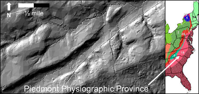
Figure 2-1. LiDAR image illustrating physiographic expression of metamorphic terrane including northeast-southwest trend in landscape.
2.1.3 Bedrock Lithology and Stratigraphy
Rock types and their specific lithologies and stratigraphy directly influence primary porosity (matrix), secondary porosity (fractures), fracture characteristics (orientation, aperture, infilling, length, planarity, roughness, connectivity, density, and the physiography), of an area or region. Determining the types of rock underlying a site and the surrounding area, therefore, is key to understanding fate and transport of contaminant. For instance, the lithology of underground mined ore bodies is invaluable information for characterizing a site. The position of ore zones is linked with underground mine workings or voids used to access the ore. As a result, the voids provide conduits for movement of water and air through barometric pumping, resulting in oxidation of the mineralized ore zones and generation of metal-laden and often acidic groundwater plumes.
This guidance provides a more detailed description of specific lithologies, including subcategories, mineralogy, porosity characteristics, associated drainage patterns, and hydrogeologic implications. USEPA’s Contaminated Site Clean-Up Information webpage (CLU-IN) provides pictorial examples of various rock types, their physical descriptions, and hydrogeologic characteristics.
2.1.4 Structural Geology and Tectonic Setting
Compressional, extensional, decompression, and shear forces may result in several types of faults and features: normal, reverse (thrust) and strike slip, brecciated zones, foliation, inclined/folded sedimentary bedding, rift zones, or tabular intrusions. These distinct structural features influence fluid flow. These characteristics can be determined from evaluating desktop resources such as tectonic, geologic, and physiographic province maps, and supplemented by field reconnaissance. Structural characteristics commonly associated with rock types are summarized in the terrane analysis matrix.
Many tectonic structures are the result of either compression, extension, or shearing of the rock and tend to form parallel or at a predictable angle to the main stresses imposed on the rock, as shown in Figure 2-2. Tensional fractures are common in anticline, syncline, and isostatic rebound zones and should be considered as part of the site characterization, migration pathways, and drilling techniques (link Appendix C). Figure 2-2 illustrates the three primary types of faults (reverse, normal, and strike-slip) that form as a result of compression, extensional, and shear forces.
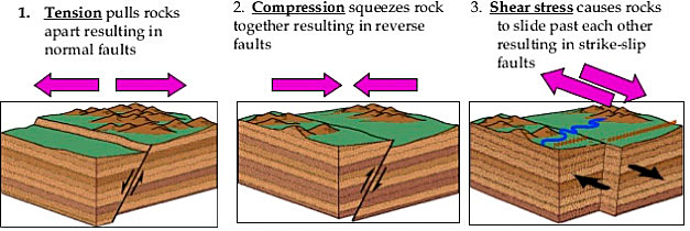
Figure 2-2. Reverse, normal, and strike slip faults due to compression, extensional, and
shear forces.
Source: U.S. Geological Survey Department of Interior.
The following example illustrates how the structural geologic history of an area is used to predict type, orientation, distribution, and intensity of geologic discontinuities. The Triassic Basin in Virginia (Figure 2-3) was created by extensional tectonic forces. In this rift structure, gently dipping beds and extensive, subvertical fracturing can be expected. Investigation activities can then be designed to locate and verify these geologic discontinuities.
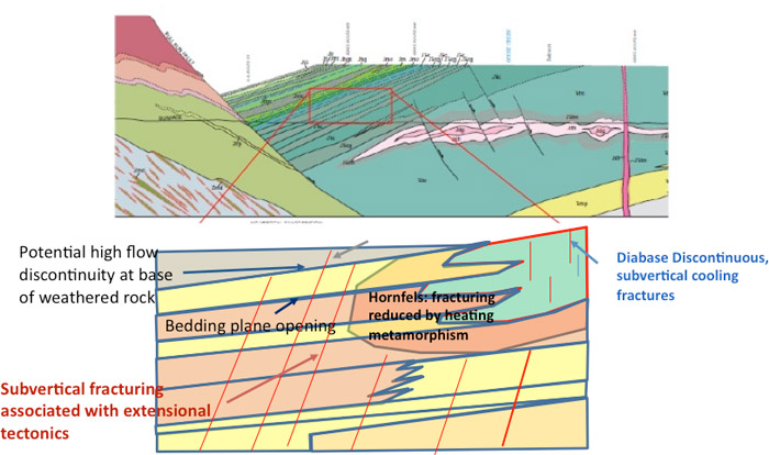
Figure 2-3. Tectonic and structural characteristics of the Triassic Basin in Virginia.
Compressional forces result in folding as illustrated in Figures 2-4 and 2-5. The folding of the rocks create a range of joints and other discontinuities whose orientations can be predicted if the geologic stress history is understood.
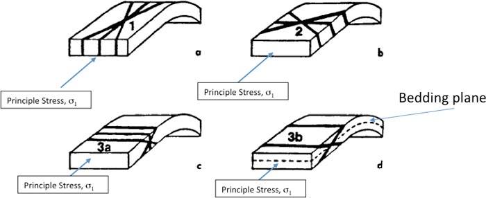
Figure 2-4. A generalization of dominant fold-related fracture or joint sets.
Source: (Stearns 1968)
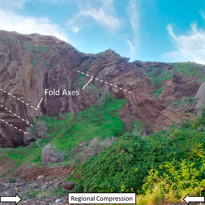
Figure 2-5 Intense folding of sedimentary rocks due to compressional forces with jointing along fold axis. Groundwater flow impeded left to right across page. Preferential groundwater flow along strike of folds into/out of page.
2.1.5 Heterogeneity and Anisotropy
Knowledge of the rock type and of the associated structure and tectonic history are combined to determine the expected degree and geometry of anisotropy and heterogeneity that may occur within the terrane. Heterogeneity in fractured rock is the condition where, for a given property (usually hydraulic conductivity), there is a spatial variability and the rock properties are different at various locations. This condition is in contrast to homogeneity, which refers to the condition in which one or more properties are the same at all locations. Anisotropy should be considered when assessing groundwater fracture flow direction due to structural or stratigraphic orientation. Intrusive (Link Appendix C) investigations may be guided by the suspected preferential flow direction due to anisotropy.
The terrane analysis matrix indicates the degree of anisotropy and potential for heterogeneity within aquifers consisting of a variety of rock types and subjected to differing degrees of structural/tectonic deformation, dissolution processes, intrusive/extrusive processes, and thermal history. Figure 2-6 illustrates the characteristics and differences of isotropy, anisotropy, homogeneity, and heterogeneity.
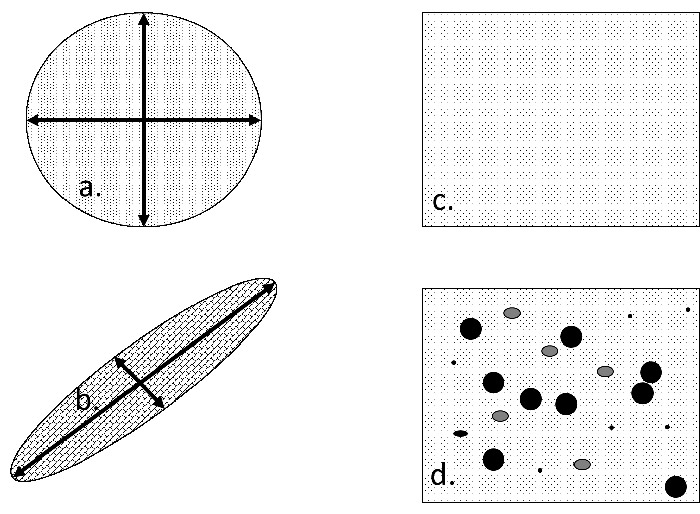
Figure 2-6. Hydraulic conductivity (K) in an aquifer: a) Isotropy – K is the same in all locations. b) Anisotropy – K is significantly greater in the NE/SW directions. c) Homogeneity – K is the same at all locations (top right). d) Heterogeneity – K is different at different locations.
2.1.6 Hydrology
Surface water features (such as creeks, streams, rivers, lakes, seas, and oceans) represent hydraulic boundary conditions (discharge or recharge boundaries, for example) that influence groundwater flow directions and hydraulic gradients within the physical framework consisting of the lithology, structure, and topography. Surface water features often reflect the geologic terrane, fabric, and underlying structural geology. In some cases, however, local recharge to surface water may occur but regionally may flow beyond the local boundary. Appendix B Table B-1, illustrates types of drainage patterns (surface hydrology) that occur with various terranes and underlying rock types and structures. Figure 2-7 illustrates an example of the superposition of a surface water drainage within the geologic terrane, which has developed preferentially along the strike of schist foliation. General hydrology information can be obtained from USGS topographic maps. More detailed hydrology is often necessary for the specific site, which can be obtained with LiDAR data, aerial photographic imagery, field reconnaissance (for example, ground truthing) or GPS data, and then developing hydrology line work using ArcGIS or similar programs combined with GIS software.
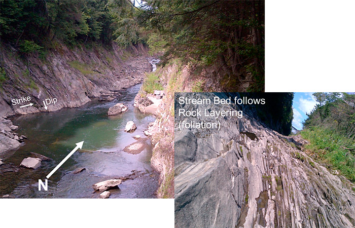
Figure 2-7. Stream valley eroded into tilted layers of rock (schist).
2.2 Benefits of Terrane Information for the Initial CSM
Terrane analysis is used to develop an initial terrane-based CSM framework. As part of this effort, it is important to consider the following: relative geometry of hydraulic boundaries, hydraulic gradient, rock fabric orientation, degree of weathering and contaminant sources and receptors, including where groundwater saturation occurs relative to the physical setting and the overburden/ bedrock interface. Figure 2-8 shows initial terrain CSM examples that illustrate the potential relative influences of the six elements.
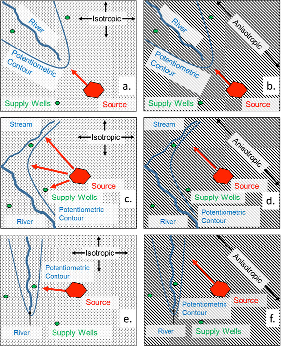
Figure 2-8. Initial CSM examples of contaminant source, flow direction, hydraulic boundaries, and receptors. Red arrows indicate flow direction but not magnitude of velocity or hydraulic gradient. a) Isotropic flow orthogonal to hydraulic gradient, no supply wells affected. b) Anisotropic flow orthogonal to hydraulic gradient, no supply wells affected. c) Radial isotropic flow orthogonal to hydraulic gradient, supply wells potentially affected. d) Linear anisotropic flow to a tributary stream, supply well potentially affected. e) Isotropic flow orthogonal to hydraulic gradient, supply well potentially affected. f) Anisotropic flow, oblique to hydraulic gradient, supply well not affected.
2.3 Terrane Analysis Case Study
Without a terrane analysis, potential receptors can be missed. In addition, the bedrock geochemistry should be considered for its potential effect on contaminant migration. A terrane analysis case study that was verified and validated through high density intrusive characterization is presented in Figure 2-9. This example highlights each element of the terrane analysis matrix.
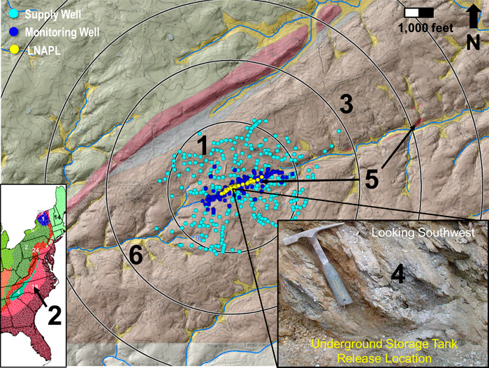
Figure 2-9. Case study demonstrating terrane-influenced migration of LNAPL within foliated, metamorphic rock and trellis drainage system surrounded by groundwater supply wells. Elements of terrane analysis matrix are denoted by number: 1) potential receptors, 2) physiographic province, 3) lithology, 4) structure, 5) anisotropy / heterogeneity, 6) hydrology. Concentric circles represent radii from release in ½ mile increments.
The elements of the terrane analysis case study are described in terms of the six components of the terrane analysis matrix:
- Potential Human and Ecological Receptors. Potential receptors include private supply wells installed into bedrock and streams incised into bedrock that are hydraulically connected to groundwater. Contaminant vapors could migrate through bedrock fractures and present vapor intrusion issues.
- Regional Physical Setting. The site is located within the Piedmont Physiographic Province. The map of physiographic provinces (Figure 2-1) shows that the Piedmont has a northeast-southwest structural trend. According to the USGS (Swain 2004):
“The Valley and Ridge, Blue Ridge, and Piedmont Physiographic Provinces are underlain by metamorphic, igneous, and sedimentary rocks; gneiss, schist, granite, and siliciclastic sedimentary rock underlie almost two-thirds of the study area [Lithology]. Following faulting and folding, as well as one or more periods of metamorphism and igneous intrusion [Structural Geology and Tectonics] of the rocks in most of the study area, the entire area was uplifted during the Cenozoic Era. Subsequent weathering and erosion enlarged existing fractures in the bedrock and may have created new fractures by stress relief.”
The aquifers of the Piedmont Physiographic Province are a major source of drinking water supplies in the Eastern United States, with documented transmissivity values for terranes in the Piedmont range from 9 to 1,400 ft2/d (Swain 2004).
- Lithology. The lithology of the case study area consists of the metamorphic rocks gneiss, quartzite, marble, and schist. The site itself is specifically located within schist (crystalline, metamorphic rock exhibiting foliation).
- Structure. The foliation of the schist is the predominant structural characteristics, which strikes northeast and dips northwest, imparting a regional fabric to the terrane.
- Anisotropy and Heterogeneity. The structural orientation of the schist results in anisotropy that strongly influences the direction of groundwater flow and contaminant migration (northeast and southwest) along foliation strike. The local occurrence of gneiss within the schist provides an element of heterogeneity.
- Hydrology. The characteristic trellis drainage pattern associated with foliated metamorphic terrane is evident in Figure 2-10. These streams provide hydraulic influence on groundwater flow as discharge boundaries (potential surface water receptors with fixed head conditions). The physiography is influenced by differential weathering and erosion, which has resulted in more resistant ridges and less resistant valleys where streams occur.
2.4 Terrane Analysis Summary
The example terrane analysis illustrates that foliation of the bedrock, which is expressed as regional terrane fabric (northeast-southwest trending ridges, valleys, geologic contacts, and streams) influenced the direction of contaminant migration to be linear to the northeast and southwest. The hydraulic gradient for groundwater flow in this terrane is toward the headwaters of streams that are also aligned northeast-southwest according to the foliation and regional terrane fabric. Many potential supply-well receptors exist in the area, but few are affected due to the terrane influence on contaminant migration and groundwater flow.
The terrane analysis provides an initial hydrogeologic framework (initial CSM), which, when incorporated into the CSM, can be used to guide and direct subsequent site investigation, remediation, and risk management measures. Subsequent work is necessary to understand and validate site-specific characteristics of fracture flow, further development of a sufficiently detailed and actionable CSM, and the assessment using the 21-compartment model.

